|
This install will walk you through installing a Laguna Driftmaster Fence on a MiniMax MM20 bandsaw. This will
replace the factory fence supplied by MiniMax. I choose to install the handwheel on the right side of my fence
rail. This allows an unobstructed opening of the lower door.
The format for this install will be picture shown followed by the instructions for that picture. Let's Begin.
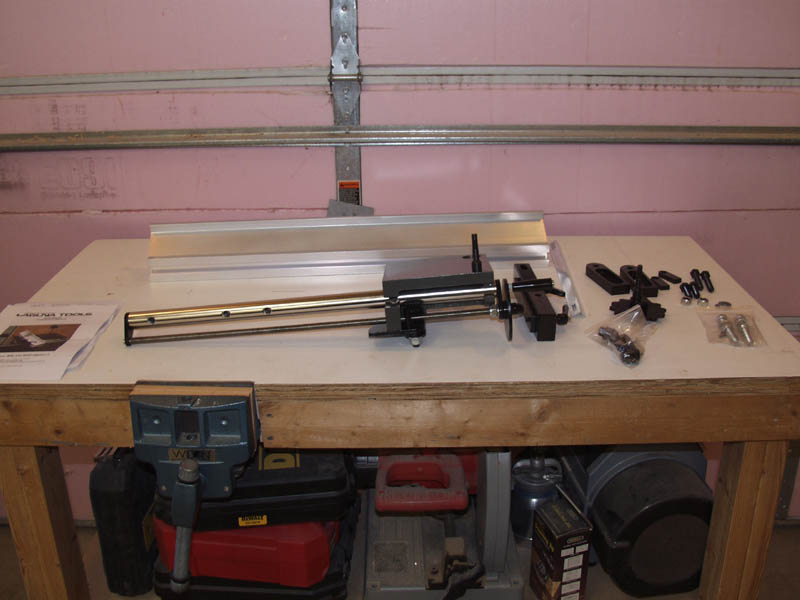
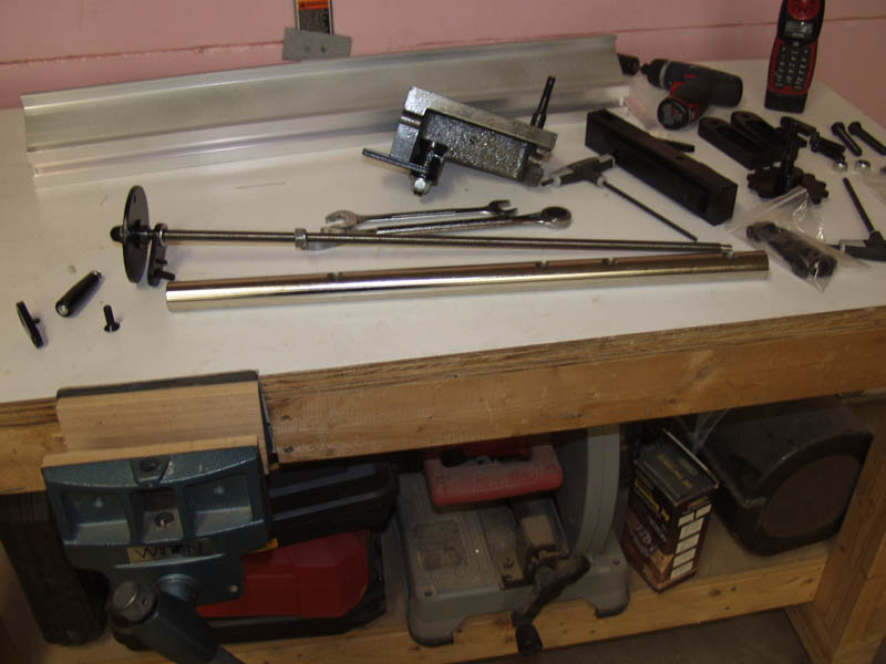
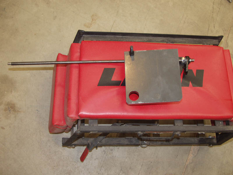
Here are the pieces that ship with the Driftmaster. I will be doing an install using the universal install brackets that
ship with the fence. These allow for quite a bit of adjustability during the install. For the Mini Max MM20 bandsaw, you
will have to drill two holes on the front edge of the table to allow for mounting bolts to be installed.
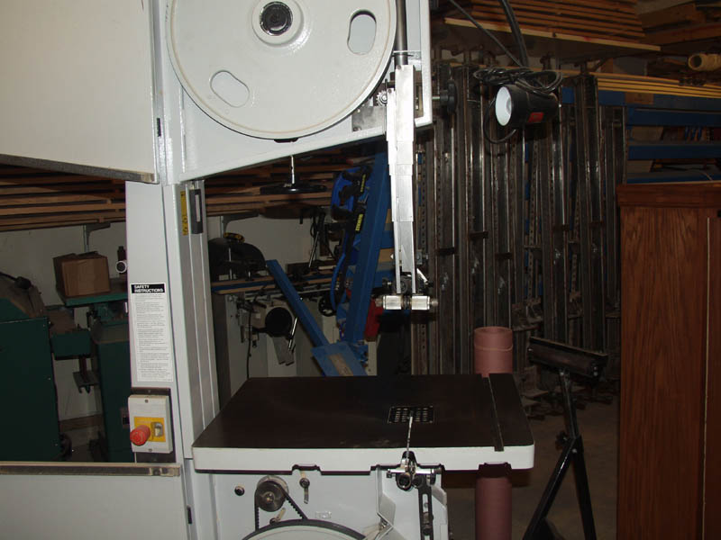
Remove the factory fence rail by unbolting two bolts under the table. Set the fence and fence rail out of the
way. Make sure you are working on a clean bandsaw table and table edge.
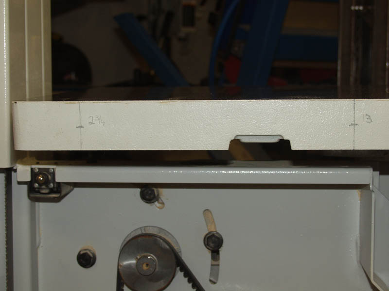
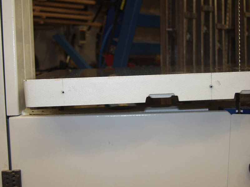
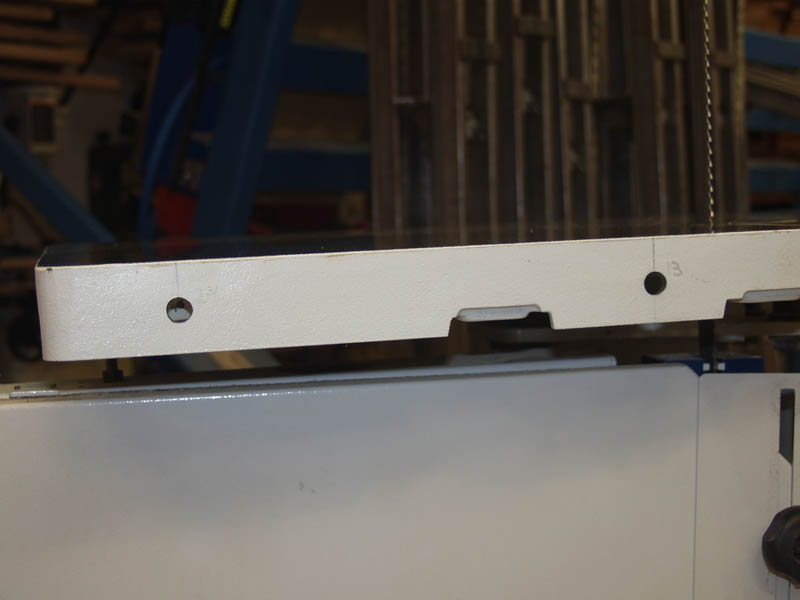
For my install I choose to use hole spacing at 2 3/4" and 13". These holes are placed in the middle widthwide of the
table. Mark the holes and then used a punch to dimple the paint and cast iron. This makes starting the holes much easier with
a drill.
It is VERY EASY to drill cast iron with a set of sharp regular drill bits. Make sure to go slow, have patience, DO NOT
JUMP BIT SIZES TOO AGGRESSIVELY, and keep steady solid control of your drill.
Start with a small drill bit size, about 1/8" and then progress through your set of bits until you finished the
hole with a 1/2" diameter bit. Here are two pictures of that progression. The actual progression was about 10 different
size holes up to 1/2". Try and drill your holes as level as possible.

This is the final size hole, 1/2". I am showing the drill I used and the regular bits I used as well. Very simple.
Back at the bench, go ahead and disassemble the fence.
The goal is to take everything off the main chrome rail.
First remove teh fence attachemnt bar by unscrewing the two lock handles, removing teh two washers and also removing
the cam bolt.
Using a #5 allen wrench you can take off the right side (as pictured) end bracket. Make sure the lock handle (under the
black main fence plate) is unlocked, and that the acme screw engagement handle is disengaged from the acme screw (perpendicular
to the rod - pointed towards you and not the handwheel). Once that is done the main plate can be slid off the chrome rail
and acme screw.
You can then move the nylon lock nut that is on the acme screw (by the handwheel) to the right using a 19mm wrench.
This allows you room to slide the acme rod to the left and access the second #5 allen headed screw.
(Not Shown - Alternatively you can use a small impact and remove the end cap nut and just remove
the handwheel - this is now my preferred way to remove the left side end bracket and shown this way later in the
walkthrough).
NOTE: The end brackets and handwheel are reversed in the reassembly to put the hand wheel on the right. Their names will
change accordingly in the walkthrough.
Once that bracket is removed, the acme screw is also freed from the chrome rail. You should now have a stand alone
chrome rail.
Set all the parts aside.
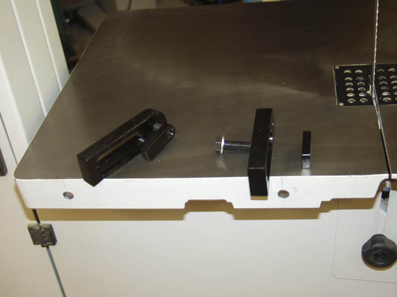
Next we will attach the posts and brackets to the table. You will see the larger brackets, two shorter bolts, two washers,
and two small nut brackets.
I have pictured the order and orientation of these parts. Place a washer on the small bolt, push it through the hole
of the larger bracket making sure the bracket recess faces the table edge, insert that through the hole you drilled in the
table, and thread it into a small nut bracket under the table. That nut backet will rotate up and lock in place
while you tighten the bolts.
Using a 19mm wrench snug up the brackets to the table (do not over tighten).
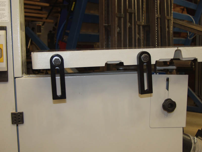
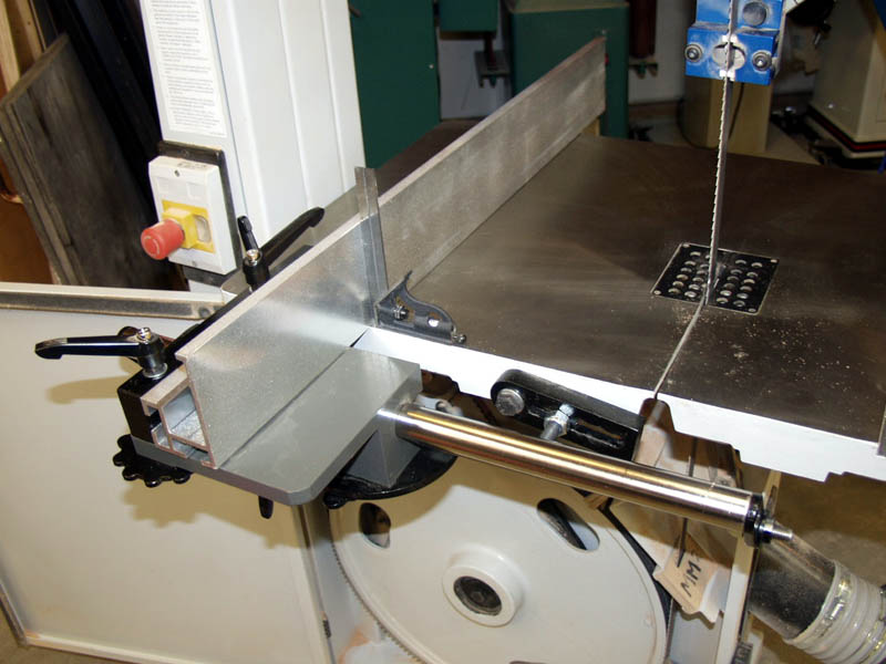
This is what it looks like when both brackets are installed.
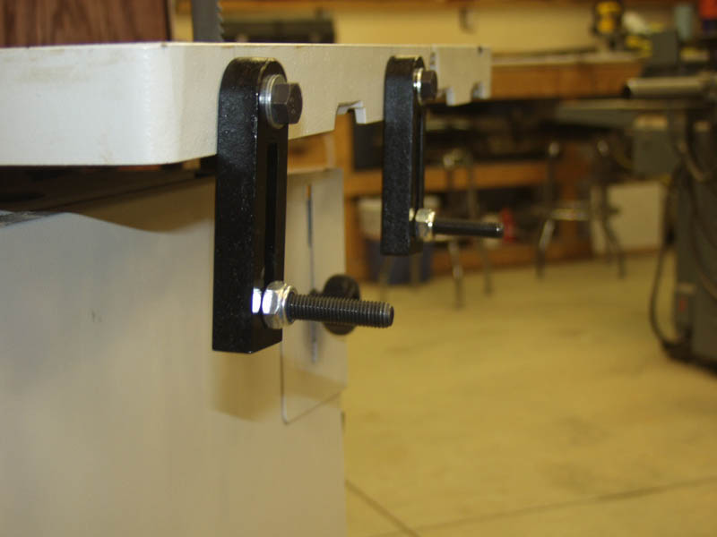
Next take the two longer bolts, place a washer on them, slide them through the bracket slots from the inside, and screw
on a nylon lock nut. The bolt heads are 18mm and the nylon lock nut is 19mm. Screw that nylon lock nut on almost all
the way until it just about is snug but can still freely slide up and down in the slot.

Next take the chrome rod, and thread the left slotted bracket bolt into the chrome rod. The hole selection is important
so make sure you choose the hole that is farthest from the end. This hole is shown above, four pictures above, on the
left.
Thread the second slotted bolt into the second hole from the end on the chrome rod.
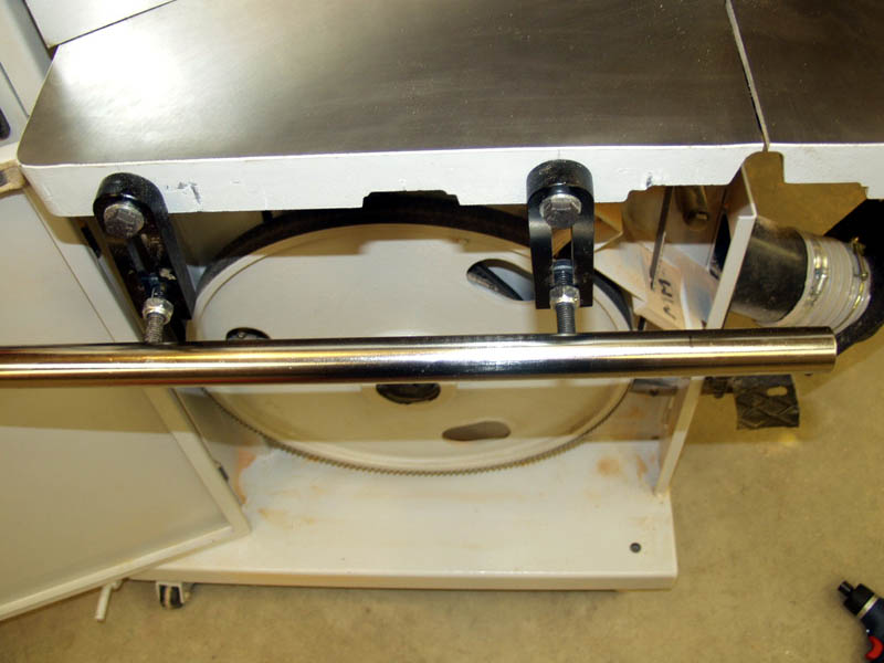
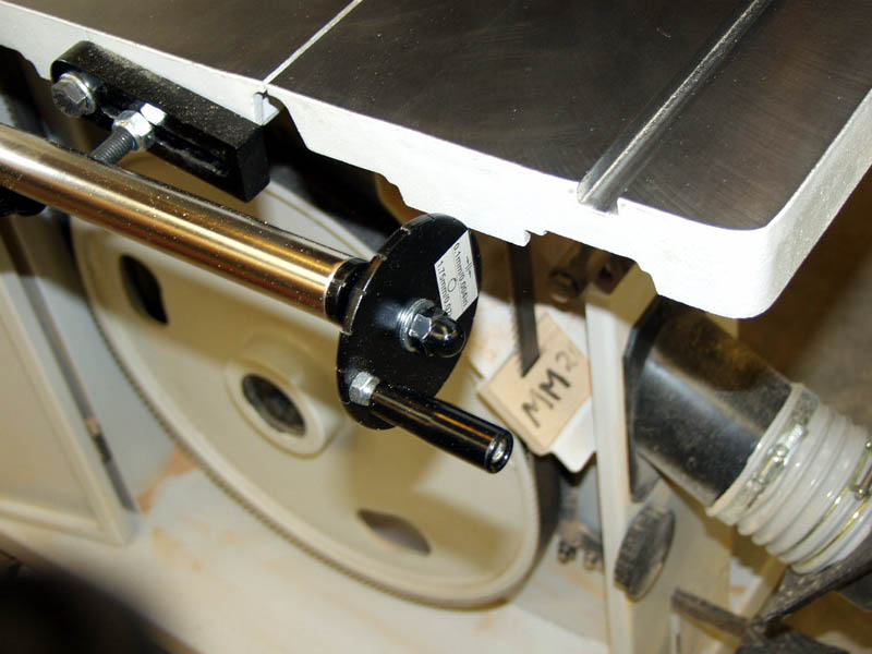
Here is a picture from the back side of the bandsaw table showing the holes that are used to connect slotted
bolts to the chrome rod.
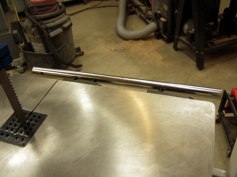
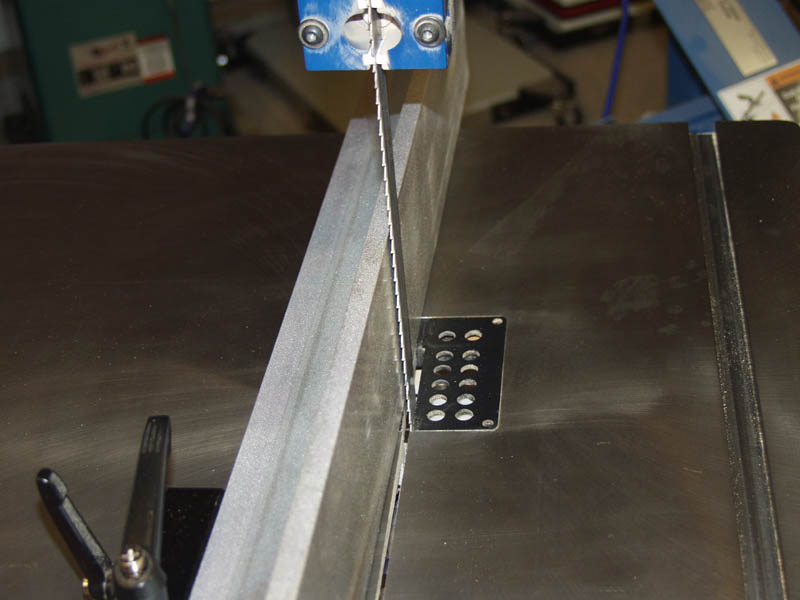
Make a mark on the rod with a marker at about 4 1/4" (look close on the right of the tube in the above picture for the
black mark). This mark will be aliged with the blade slot in the table. This is an important measurement as it allows you
enough room for the fence assembly to come all the way to the blade during use without the fence's main bracket reaching the
end of the rail and binding on the handwheel.

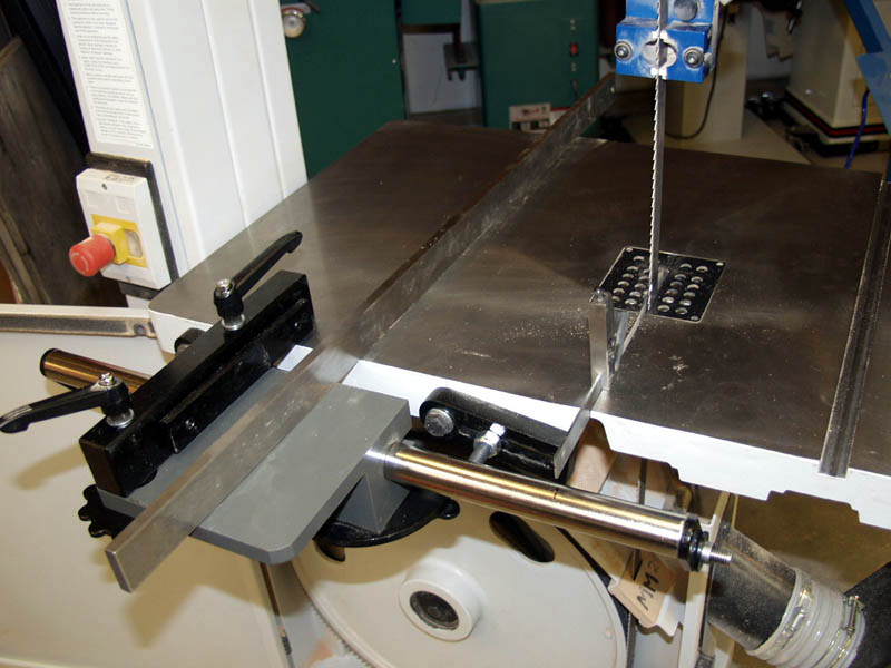
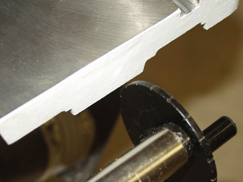
Loosend the table bolts a bit and raise the chrome rod up into position with the brackets rotated to the right. Align
the mark on the rod with the table's blade slot using a square. Keep the mark just to the right of the slot.
Make sure the brackets are positioned at about the same spot on teh edge of teh table, aproximately 1/2" from teh top
of teh table edge. Snug up the table bolts using the 19mm wrench. You want them pretty snug so they do not move
easily but not fully tightned down as we will adjust them slightly when me tune the position of the fence.
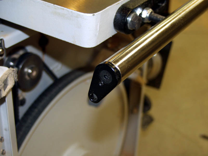
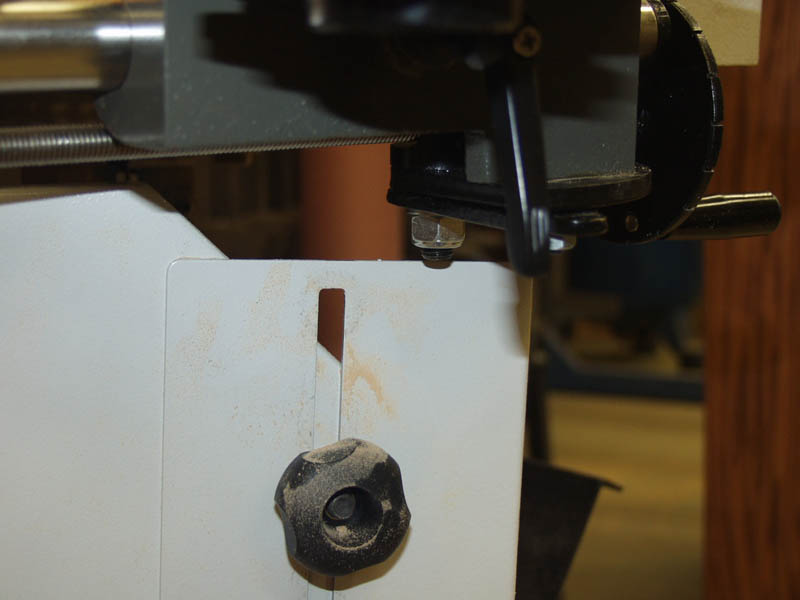
Next install the black end bracket on the left side of the chrome bar. Use a 5mm allen wrench. Make sure the bracket's
position set screw is correctly oriented in the hole of the chrome tube.
I removed the handwheel from the acme screw in this photo. I also returned the nylon lock nut back to its original
position using a 19mm wrench.
At this point install the acme screw back through the fence plate. Position it through the smaller hole with its end
bracket on the right side of the plate (opposite side of the large hole in the top that is used for the cam drift adjustment).
Look at the picture for orientation of the screw through the plate.
Take the screw and plate assembly and install it on the right side of the chrome rod. Slide the chrome rod throgh the
plate and insert the left end of the acme screw into the left end bracket (previously installed on the left end of the chrome
rod).
Insert the the allen screw through the right side end bracket and screw it down into the chrome rod using a
5mm allen wrench.
Reinstall the fence attachment bar using the lock down handles, the cam bolt, and washers.
Using a straight edge and a square, align the plane of the top of the fence plate with the band saw table top. Do
this across the face of the table top. Once flat and square, make sure the fence moves smoothly left and right across
the rail.
Make sure the acme screw engagement bracket engages smoothly, and that the screw when rotated index moves the fence smoothly both
left and right.
When everything is tuned, tighten down the table bolts and the nylon lock nuts on the slotted posts.
Install the fence. Loosen the left side lock handels so you can slide the fence on. Use a square and verify that the
fence face is 90 degrees to the table top. If not adjust so that it is square and perpendicular. You can also test out
the functionality of the Cam.
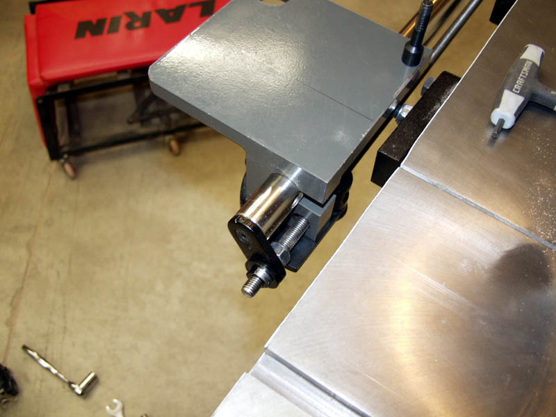
Reinstall the handwheel You should have 3/16" or so clearence between teh handwheel and the table edge. It is plenty
of room to slide a bandsaw blade by during a blade install or removal.
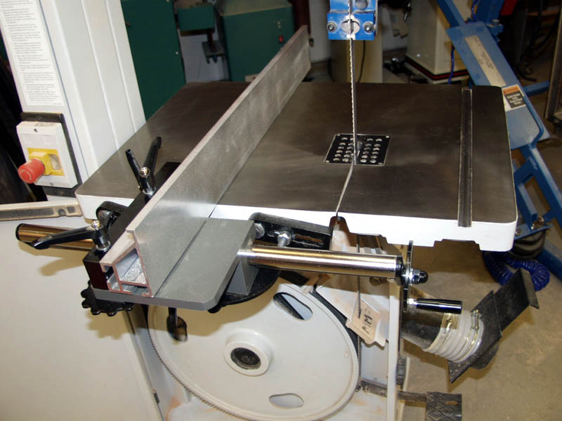
YOU FENCE IS NOW INSTALLED!!!
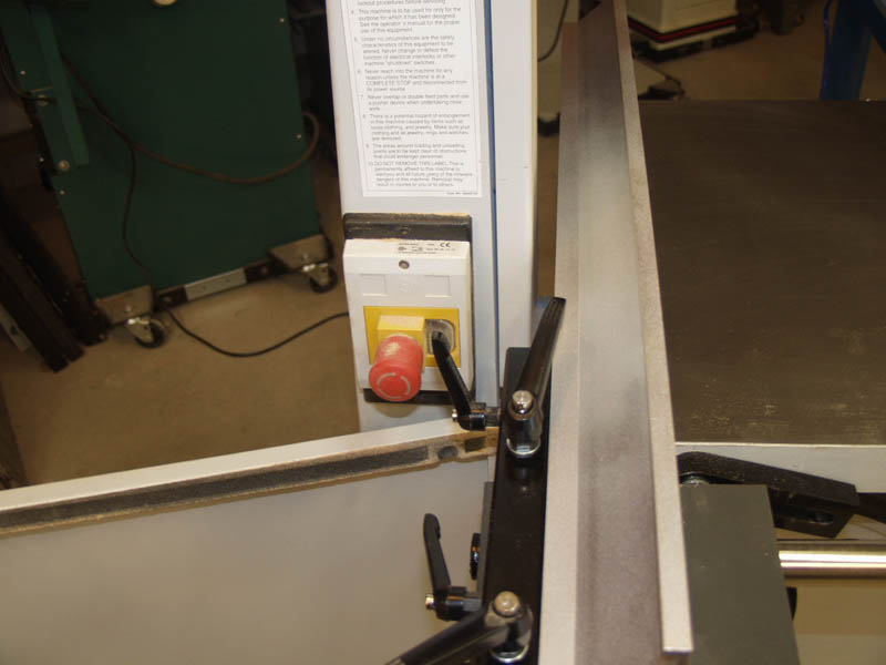
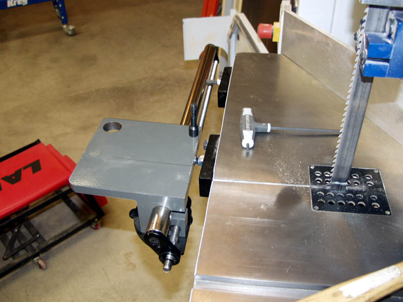
You can see the extents that the fence can move too.
You can also see that when the fence is moved to the right, the door clears the plate assembly just fine and allows you
to fully open your door for easier blade changes.
|